
The essential components of any computer system are processor, memory, and I/O devices (peripherals). The processor fetches instructions (opcodes and operands/data) from memory, processes them, and stores the result in memory. The other components of the computer system (I/O devices) may be loosely called the Input/Output System. The primary function of an I/O system is to transfer information between the processor or memory and the outside world.
Input / Output System
The Input/Output system has two major functions:
- Interface to the processor and memory via the system bus,
- Interface to one or more I/O devices by tailored data links
For a clear understanding refer to the figure below. Links to peripheral devices are used to exchange control, status, and data between the I/O system and the external devices.

An important point to be noted here is that an I/O system is not simply mechanical connectors for connecting different devices required in the system to the system bus. It contains some logic for performing the function of communication between the peripheral (I/O device) and the bus. The I/O system must have an interface internal to the computer (to the processor and memory) and external to the computer (to the external I/O devices).
Requirements of I/O System
The I/O system is nothing but the hardware required to connect an I/O device to the bus. It is also called the I/O interface. The major requirements of an I/O interface are:
- Control and Timing
- Processor Communication
- Device Communication
- Data Buffering
- Error Detection
All these requirements are explained here. The I/O interface includes control and timing requirements to coordinate the flow of traffic between internal resources (memory, system bus) and external devices. Processor communication involves different types of signal transfers such as
- The processor sends commands to the I/O system which are generally the control signals on the control bus.
- Exchange of data between the processor and the I/O interface over the data bus.
- The data transfer rate of peripherals is often much slower than that of the processor. So it is necessary to check whether the peripheral is ready or not for data transfer. If not, the processor must wait. So it is important to know the status of the I/O interface. The status signals such as BUSY, READY can be used for this purpose.
- A number of peripheral devices may be connected to the I/O interface. The I/O interface controls the communication of each peripheral with the processor. So it must recognize one unique address for each peripheral connected to it.
The I/O interface must be able to perform device communication which involves commands, status information, and data.
Data buffering is also an essential task of an I/O interface. Data transfer rates of peripheral devices are pretty higher than that of processors and memory. The data coming from memory or processor are sent to an I/O interface, buffered, and then sent to the peripheral device at its data rate. Also, data is buffered in the I/O interface so as not to tie up the memory in a slow transfer operation. Thus the I/O interface must be able to operate at both peripheral and memory speeds.
I/O interface is also responsible for error detection and reporting errors to the processors. The different types of mistakes are mechanical electrical malfunctions reported by the device, such as lousy disk track, unintentional changes to the bit pattern, transmission errors, etc. To fulfill all these requirements, the essential blocks necessary in any I/O interface are shown down below figure.
The above figure shows that the I/O interface consists of a data register, status/control register, address decoder, and external device interface logic. The data register holds the data being transferred to or from the processor. The status/control register contains information relevant to the operation of the I/O device. Both data and status/control registers are connected to the data bus. Address lines drive the address decoder. The address decoder enables the device to recognize its address when it appears on the address lines. The external device interface logic accepts inputs from the address decoder, processor control lines, and status signal from the I/O device and generates control signals to control the direction and speed of data transfer between the processor and I/O devices.
The above figures show the I/O interface for the input and output devices. Here, for simplicity, the block schematic of the I/O interface is displayed instead of detailed connections. The address decoder enables the device when its address appears on the address lines. The data register holds the data being transferred to or from the processor. The status register contains information relevant to the operation of the I/O device. Both the data and status registers are assigned with unique addresses and connected to the data bus.
I/O Ports
The simplest form of the I/O interface is an I/O port. The data transfer between the microprocessor and the input device is done with the help of the input port. The data transfer between the microprocessor and output device is done with the help of the output port.
Input Port
It is used to read data from the input device, such as the keyboard. The simplest form of the input port is a buffer. As shown in the figure below, the input device is connected to the microprocessor through a buffer. This buffer is a tri-state buffer, and its output is available only when the enable signal is active. When a microprocessor wants to read data from the input device (keyboard), the control signals from the microprocessor activate the buffer by asserting enable input of the buffer. Once the buffer is enabled, data from the input device is available on the data bus. A microprocessor reads this data by initiating a read command.
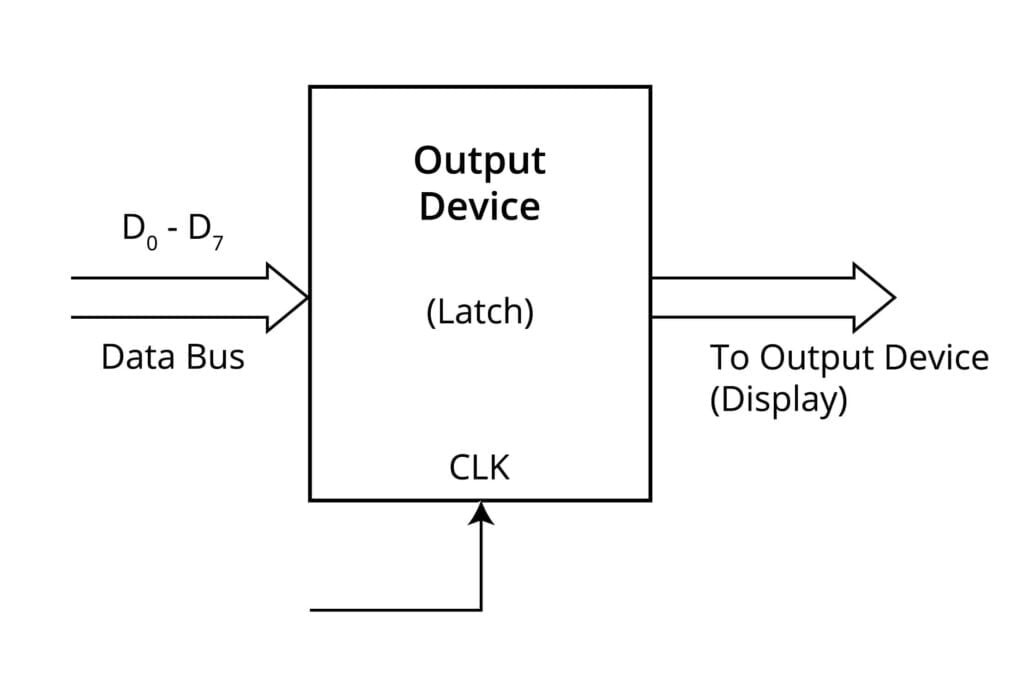
Output Port
It is used to send data to the output device, such as a display from the microprocessor. The simplest form of the output port is a latch. The output device is connected to the microprocessor through a latch, as shown below. When the microprocessor wants to send data to the output device, it puts the data on the data bus and activates the clock signal of the latch, latching the data from the data bus at the output of the latch. It is then available at the output of the latch for the output device.
I/O Data Transfer Techniques
In I/O data transfer, the system requires the transfer of data between I/O devices and microprocessors using the I/O interface. It uses various techniques to perform I/O operations. These are:
- Program Controlled I/O or Programmed I/O or Polled I/O.
- Interrupt Driven I/O.
- Hardware Controlled I/O or DMA.
Comparison Between Programmed I/O and Interrupt Driven I/O
The table below gives the comparison between programmed I/O and interrupt-driven I/O.
| Programmed I/O | Interrupt Driven I/O |
|---|---|
| In programmed I/O, the processor has to check each I/O device in sequence and in effect ‘ask’ each one if it needs communication with the processor. This checking is achieved by a continuous polling cycle and hence processor can not execute other instructions in sequence. | External asynchronous input is used to tell the processor that the I/O device needs its service and hence processor does not have to check whether the I/O device needs its service or not. |
| During polling, the processor is busy and therefore, has a serious and decremental effect on system throughput. | In interrupt-driven I/O, the processor is allowed to execute its instructions in sequence and only stop to service the I/O device when it is told to do so by the device itself. This increases system throughput. |
| It is implemented without interrupting hardware support. | It is implemented using interrupt hardware support. |
| It does not depend on interrupt status. | The interrupt must be enabled to process interrupt-driven I/O. |
| It does not need the initialization of the stack. | It needs the initialization of the stack. |
| System throughput decreases as the number of I/O devices connected to the system increases. | System throughput does not depend on the number of I/O devices connected to the system. |